
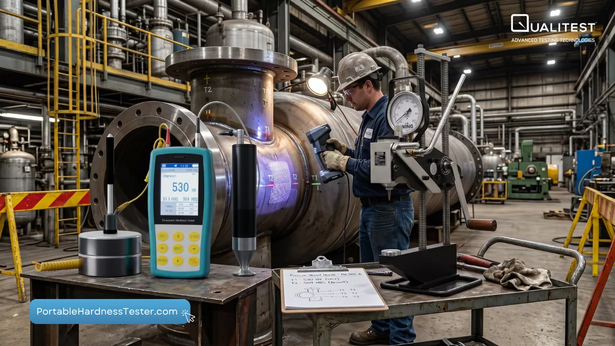
Operated assets like pipelines, pressure components, and welded systems experience material changes over time. Factors such as aging, local heating, repairs, and environmental stress modify the properties of these structures. Assessing these changes without removing samples from the site allows for more frequent and efficient monitoring of structural integrity.
Why Hardness Testing Alone Is Useful, But Not Always Enough
Portable hardness tests provide a baseline for assessing metal conditions on-site. However, relying solely on a single hardness number or force-depth data can limit the depth of the analysis. A study suggests that analyzing the physical shape of the residual imprint provides a more complete picture of material degradation and constitutive behavior.
How Hardness Imprint Mapping Works
This diagnostic method follows a specific logical sequence:
- Indentation: A hardness test creates a permanent residual imprint on the surface.
- Plastic Deformation: The shape of this imprint reflects how the material responded to stress.
- Measurement: A 3D scan captures the exact geometry of the deformation.
- Comparison: The scanned geometry is compared against computer simulations to estimate properties like yield limits and strength-related behavior.
What Equipment Was Used
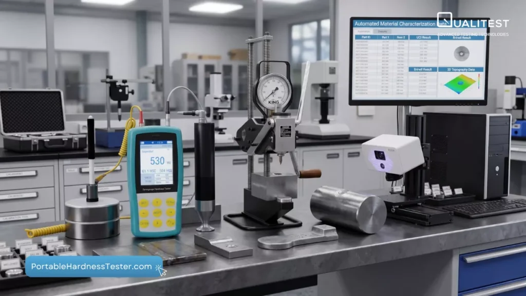
Researchers used a portable optical microscope with variable focal distance for 3D mapping. This system supports micro-topography measurements with high vertical resolution. Digital storage allows for the geometry data to be processed later, connecting field observations directly to analytical models.
Why Lower Test Loads Matter for Onsite Use
Lower testing loads improve the practicality of field work. The study compared results using 2 kilonewtons and 0.2 kilonewtons. There are several reasons why smaller loads are advantageous for technicians:
- Compact Equipment: Smaller loads allow for lighter, more portable tools.
- Scanning Speed: A smaller imprint area leads to faster image acquisition.
- Field Feasibility: Single-shot mapping becomes easier to perform in difficult environments.
How Imprint Geometry Reflects Material Condition
Plastic flow properties are most visible in the “piling-up” region around the edge of the indentation. While the bottom of the imprint reflects the shape of the testing tool, the outer deformation carries information about the material’s internal response. Mapping this outer region helps identify changes in yield and strength.
Examples of What the Method Can Detect
The method showed successful results across different materials and conditions:
- Pipeline Steel: Identified differences between reference samples and hardened X70 steel.
- Operational Aging: Detected property shifts in 17H1S steel after 36 and 51 years of active service.
How Well Did the Method Match Traditional Mechanical Testing?
Properties estimated from 3D imprint mapping showed strong agreement with traditional tensile test values. This comparison is significant for engineers because it proves that non-destructive field methods can provide data equivalent to destructive laboratory tests.
What Can Go Wrong During Onsite 3D Scanning
Real-world field conditions introduce disturbances that can affect data quality:
- Contamination: Dust or debris on the metal surface.
- Light Interference: Peaks caused by reflected light or poor lighting angles.
- Missing Data: Gaps in the scan caused by shadows or surface imperfections.
- Automatic Settings: Distortions resulting from equipment settings in non-ideal environments.
How Filtering and Regularization Improve Reliability
Advanced data processing techniques, such as proper orthogonal decomposition (POD), help separate the actual deformation pattern from background noise. Even when scans have missing data, these filtering methods allow for the reconstruction of accurate profiles. The filtered results remain close to expected trends, showing that measurement noise does not invalidate the method.
Why This Matters for Asset Integrity Programs
Implementing this workflow into maintenance routines provides several operational benefits. It supports the non-destructive diagnosis of aging assets in difficult environments and helps detect material evolution over time. This data informs repair prioritization and retrofit decisions without the need for destructive sampling.
Conclusion: A Practical Path Toward Smarter In-Situ Metal Assessment
Combining portable hardness testing with 3D scanning and robust processing creates a strong field-ready workflow. This approach simplifies the assessment of operated metal components while providing a higher level of detail than traditional methods.
Reference:
Bolzon, G., & Talassi, M. (2023). 3D Scan of Hardness Imprints for the Non-destructive In-Situ Structural Assessment of Operated Metal Components. Journal of Nondestructive Evaluation, 42, 1-13. https://doi.org/10.1007/s10921-023-00987-1.

Leave a Reply